10+ uml diagram model
UML guides the creation of multiple types of diagrams such as interaction structure and behaviour diagrams. UML short for Unified Modeling Language is a standardized modeling language consisting of an integrated set of diagrams developed to help system and software developers for specifying visualizing constructing and documenting the artifacts of software systems as well as for business modeling and other non-software systemsThe UML represents a collection of best.

Pin On Change Management
The purpose is also different from all other.

. In software engineering an ER model is commonly formed to represent things a business needs to remember in order to perform business processesConsequently the ER model becomes an abstract data model that defines a data or information structure which can be implemented in a database typically a relational database. The purpose of the class diagram can be summarized as. Hence to model the entire system a number of use case diagrams are used.
Learn about activity diagram symbols below. The diagram is used to model the systemsubsystem of an application. Above is an example of a Sequence Diagram of an Online Shopping Cart.
The 1980s were years of relative consolidation. In other words UML Diagrams are diagrams that depict how. UML stands for Unified Modelling Language.
In between there are ways to depict activities flows decisions guards merge and time events and more. In my previous article on sequence diagrams I shifted focus away from the UML 14 spec to OMGs Adopted 20 Draft Specification of UML UML 2In this article I will discuss Structure Diagrams which is a new diagram category that. Physical aspects are the elements such as executables libraries files documents etc.
Unified Modelling Language UML is a modeling language in the field of software engineering which aims to set standard ways to visualize the design of a system. A single use case diagram captures a particular functionality of a system. To understand UML Activity Diagrams we first need to understand what the UML Diagram means.
You order the layout which is persisted independent from the classes in the diagram file. Umple is an open source model for integrating textual UML constructs in programming languages code generation or using simple UML modeling method. It is the most popular UML diagram in the coder community.
The creation of UML was originally motivated by the desire to standardize the disparate notational systems and approaches to software design. Subclasses of Creator can redefine which class to instantiate. Purpose of Use Case Diagrams.
State diagrams are also referred to as State machines and State-chart DiagramsThese terms are often used interchangeably. One of the first uses of the term protocol in a data-commutation context occurs in a memorandum entitled A Protocol for Use in the NPL Data Communications Network written by Roger Scantlebury and Keith Bartlett in April 1967. UML state machine also known as UML statechart is an extension of the mathematical concept of a finite automaton in computer science applications as expressed in the Unified Modeling Language UML notation.
In a few minutes you can create a class diagram showing the actual implementation of eg. Create a C library project Map Viewer in Visual Studio. The United States government standardized Ada a systems programming language derived from Pascal and intended for use by defense contractors.
Go beyond diagramming with Power Automate Power BI Word Excel and PowerPoint integrations. Its a behavioral diagram and it represents the behavior using finite state transitions. UML stands for Unified Modeling LanguageIts a rich language to model software solutions application structures system behavior and business processesThere are 14 UML diagram types to help you model these behaviors.
Object references are interpreted as association if you want. UML is a way of visualizing a software program using a collection of diagrams. You select the classes by drag and drop.
The Unified Modeling Language UML is a general-purpose developmental modeling language in the field of software engineering that is intended to provide a standard way to visualize the design of a system. Entityrelationship modeling was developed for. A small filled circle followed by an arrow represents the initial action state or the start point for any activity diagram.
The purpose of use case diagram is to capture the dynamic aspect of a system. This interactive behavior is represented in UML by two diagrams known as Sequence diagram and Collaboration diagram. In the above UML class diagram the Creator class that requires a Product object does not instantiate the Product1 class directly.
This interaction is a part of dynamic behavior of the system. Component diagrams are used to model the physical aspects of a system. Design system with UML Class Diagram.
Instead the Creator refers to a separate factoryMethod to create a product object which makes the Creator independent of which concrete class is instantiated. A data model is an abstract model that organizes elements of data and standardizes how they relate to one another and to the properties of real-world entitiesFor instance a data model may specify that the data element representing a car be composed of a number of other elements which in turn represent the color and size of the car and define its owner. You can draw UML diagrams online using our software or check out some UML diagram examples at our diagramming community.
C combined object-oriented and systems programming. This is the next installment in a series of articles about the essential diagrams used within the Unified Modeling Language or UML. This UML diagram maker provides the best functionality expected from a UML tool like a large selection of supported diagrams.
On the ARPANET the starting point for host-to-host communication in 1969 was the 1822 protocol which defined. A sequence diagram is the most commonly used interaction diagram. Analysis and design of the static view of an application.
In this example the. Right-click on the project node in Solution Explorer and select Open Visual Paradigm from the popup menu. A new diagram is created.
Starting from the top you can see that the actor of the diagram will be the customer that logs in to the e-commerce website and adds an item to the shopping cart in order to complete the purchase. Enjoy all the features in Visio Plan 1 plus additional templates shapes and advanced features in the Visio desktop app. UML Diagram What is a UML Diagram.
The basic purpose of. Now the question is what are these physical aspects. A state diagram is used to represent the condition of the system or part of the system at finite instances of time.
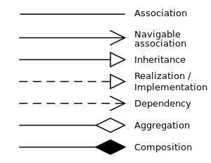
Lets take a look at the diagram and try to understand how the task is completed in the system. It is a standardized set or a collection of diagrams that helps the software developers and software architects to understand the flow of the software. Boxes and Arrows 2413.
Which reside in a node. The UML diagram has very basic features. Component diagram is a special kind of diagram in UML.
In Diagram Navigator right-click on class diagram and select New Class Diagram from the popup menu. Windows 7 8 10 versions supported. From the term Interaction it is clear that the diagram is used to describe some type of interactions among the different elements in the model.
Basic Activity Diagram Notations and Symbols Initial State or Start Point. So simply a state diagram is used to. In Japan and elsewhere vast sums were spent investigating the so-called fifth-generation languages that.
The notation has evolved from the work of Grady Booch James Rumbaugh Ivar Jacobson and the Rational Software Corporation to be used for object-oriented design but it has since been extended to cover a wider variety of software engineering projects. UML diagrams like activity diagram sequence diagram can only give the sequence flow of the application however class diagram is a bit different. The concepts behind it are about organizing the way a device computer program or other often technical process works such that an entity or each of its.

Dbms Case Study Dbms Erd Management Information Systems

Uml Diagrams What You Need To Know Diagram Sequence Diagram Class Diagram
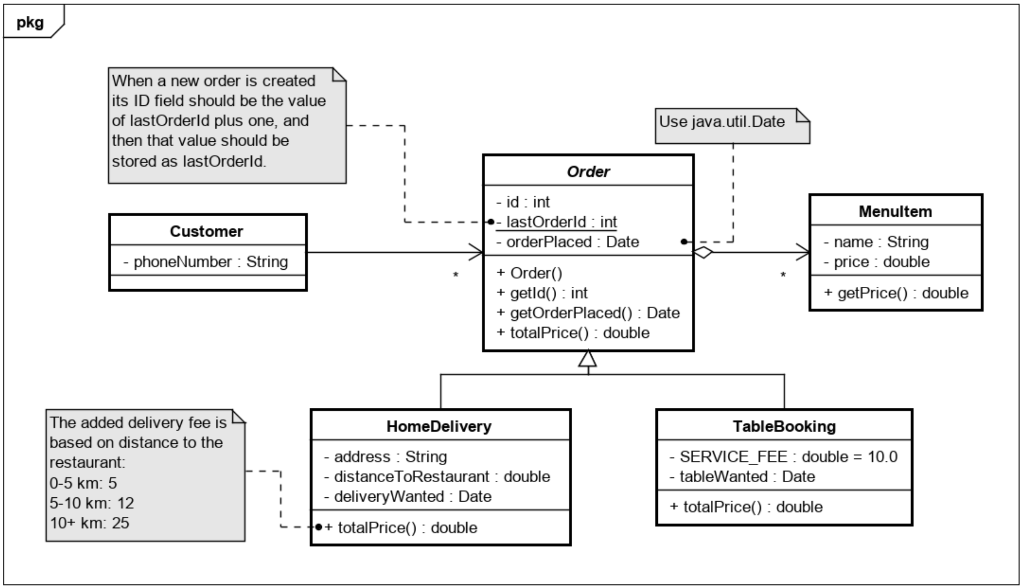
Solved I Was Given This Uml Class Diagram And Asked To Code Chegg Com

Class Diagram Wikiwand

4 Phases Of The Project Management Lifecycle Contract Management Change Management Project Management
Class Diagram Wikiwand

Uml Diagram Templates And Examples Lucidchart Blog Process Flow Chart Diagram Use Case

Dbms Case Study Dbms Web Development Tutorial Database Design

Free Editable Online Shopping Uml Sequence Diagram Edrawmax Sequence Diagram Time Diagram Class Diagram

10 Types Of Diagrams How To Choose The Right One Venngage

Uml Diagram Course How To Design Databases And Systems Class Diagram Activity Diagram Free Online Learning
Class Diagram Wikiwand

Uml Diagram Types Learn About All 14 Types Of Uml Diagrams Ingenieria De Software Lenguaje Linea Del Tiempo

Domain Diagram Overview Classes Interfaces Associations Usage Realization Multiplicity Class Diagram Database Design Programming Patterns

Xlstemplate Com User Story Template User Story Project Management Templates

Uml Class Diagram Examples Class Diagram Class Diagram

Dbms Case Study Dbms Database Design Management Information Systems